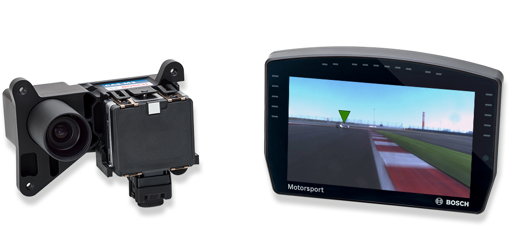
The Collision Avoidance System-Motorsport 3 EVO (CAS-M 3 EVO) features a high-performance Bosch Motorsport Display Unit for fast video processing (right in the picture), and a Rear Module, composed from a Bosch mid-range radar sensor for a wider field of view in close-up range and a fast response high definition camera (left in the picture).
The CAS-M 3 EVO system provides real time visualization and warns the driver about approaching or overtaking cars via intuitive marking of the cars on the display. It helps prevent the most common collisions and allows drivers to focus on the race. With a momentary glance, the driver can tell how many cars are following and their classification depending on distance and relative speed. The radar tracks up to 40 objects and marks up to four objects on the display. In addition, bright flashing LEDs alert the driver when any car attempts a passing maneuver. All of these features work at night or in the rain when visibility is typically poor. Furthermore, the real time gap of a marked object is measured and can be provided over CAN or Ethernet.
The CAS-M 3 EVO system is fully integrated in the Bosch Motorsport Tool environment and can be configured with RaceCon.
- Downloads
- Features
- Application
- Technical Specifications
- Communication
- Installation Notes
- Ordering Information
- Dimensions
- Legal Restrictions
Downloads
Link to the up-to-date EU Declaration of Confirmity DoC:
(Please enter the model MRRe14HBW on which CAS-M sensors are based on to find the correct DoC in the database.)
Literature
Software
Features
- Approaching vehicle tracking
- Left/right passing alerts
- Improves visibility of objects in rain, mist or darkness
- Full Bosch Motorsport tool integration
Application
Range | 95 m |
Horizontal field of view | |
Radar | 85° from 0 to 29 m 70° from 29 to 46 m 50° from 46 to 73 m 42° from 73 to 78 m 20° from 78 to 95 m |
Camera | 78° |
Number of tracked objects | Max. 40 |
Number of displayed classified objects | Max. 4 |
Display format | 7’’ |
Display resolution | 800 x 480 pixel |
User configurable CAN in/out messages | |
User configurable LEDs | |
Technical Specifications
Mechanical Data
Display Unit |
|
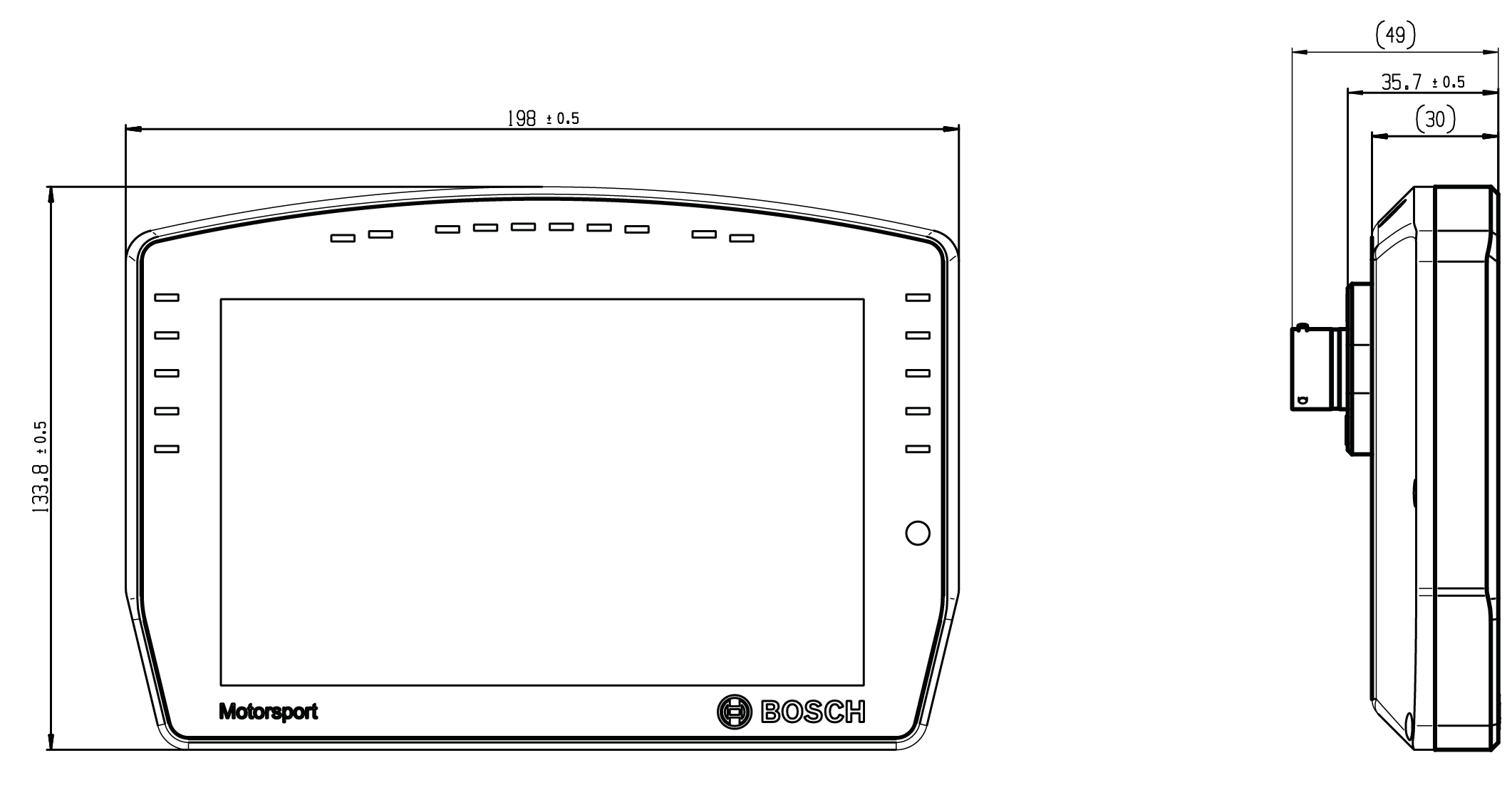
Size | 198 x 134 x 35 mm |
Weight | 830 g |
Protection Classification | IP67 |
Operating temperature internal | -20 to 85°C |
Max. vibration | Vibration profile 1 (see Downloads or www.bosch-motorsport.com) |
Rear Module |
|
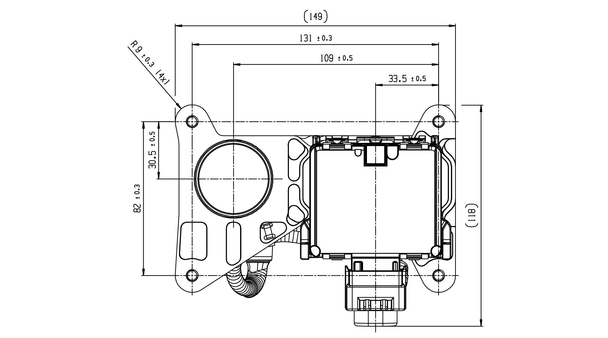
Size | 120 x 150 x 115 mm |
Weight | 880 g |
Protection classification | IP67 |
Operating temperature | 0 to 70°C (rearview camera internal temperature*) |
Max. vibration | Vibration profile 1 (See Downloads or www.bosch-motorsport.com) |
*If the temperature limit is reached, forced air cooling of the camera is recommended.
Electrical Data
Supply voltage (Display and Rear Unit) | 6 to 18 V |
Current consumption | |
Display Unit | 2 A (at 12 V) |
Rear Module | 0.7 A (at 12 V) |
Communication
Display Unit |
|
CAN | 1x private CAN for radar, |
Ethernet | 1x private 1GBase-T Ethernet for camera, |
Time sync synchronization Ethernet | 1 |
Rear Module |
|
CAN | 1x private CAN for radar |
Ethernet | 1x private 1GBase-T Ethernet for camera |
Software Tools (free download)
Data analysis tool | WinDarab 7 Light |
System configuration tool | RaceCon |
Connectors and Wires
Display Unit |
|
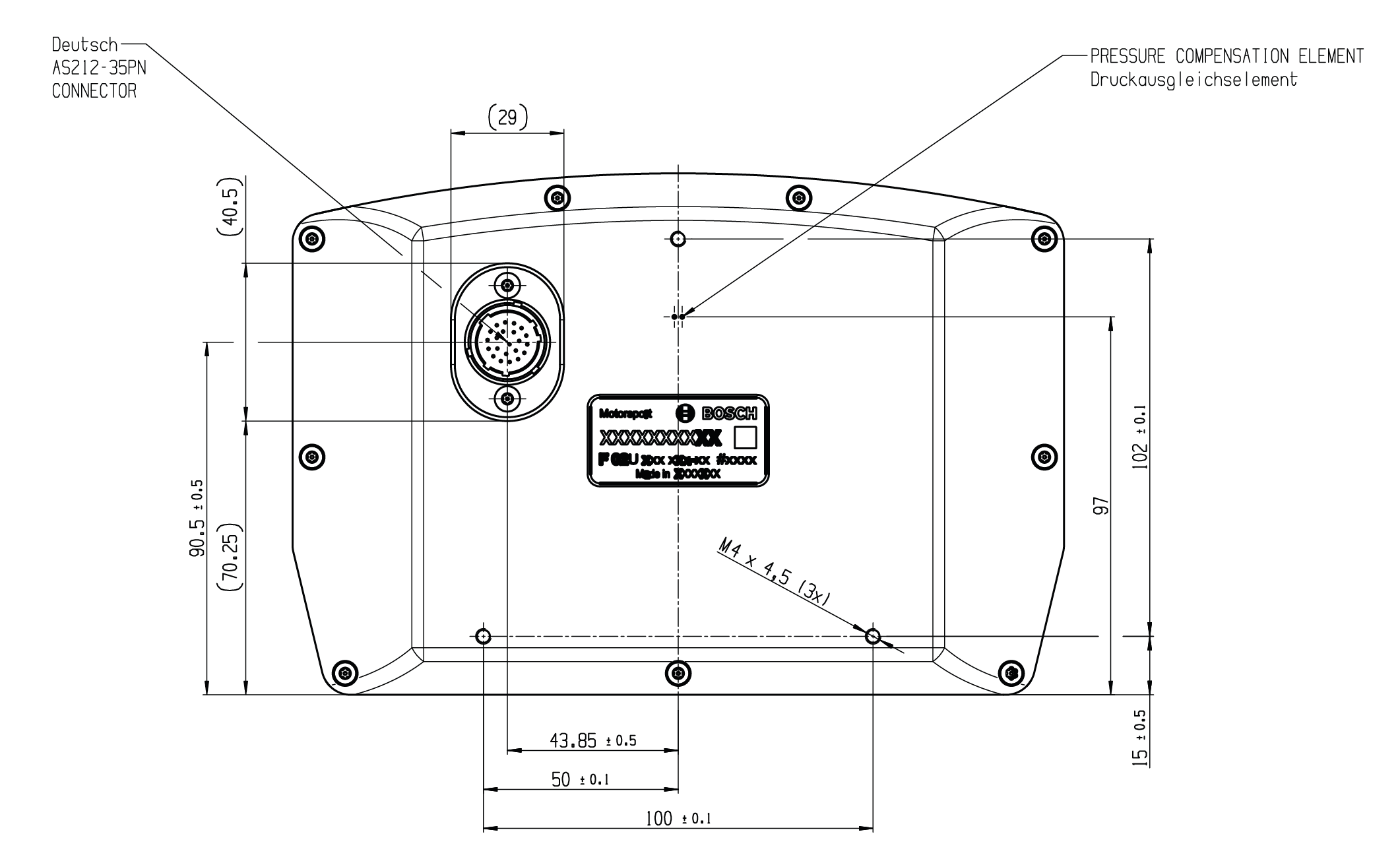
Motorsport connector on device | AS212-35PN |
Mating connector AS612-35SN | F02U.000.443-01 |
Rear Module |
|
Motorsport connector on device | AS212-35PN |
Mating connector AS612-35SN | F02U.000.443-01 |
Pin Configuration
Display Unit | Rear Module for Vehicle Harness | |
Pin No. | Pin No. | |
1 | GigEthernet_TR3_N (private Eth camera PEC) | 14 |
2 | GigEthernet_TR3_P (PEC) | 1 |
3 | GigEthernet_TR2_N (PEC) | 2 |
4 | GigEthernet_TR2_P (PEC) | 3 |
5 | GigEthernet_TR1_N (PEC) | 4 |
6 | GigEthernet_TR1_P (PEC) | 5 |
7 | GigEthernet_TR0_N (PEC) | 6 |
8 | GigEthernet_TR0_P (PEC) | 7 |
9 | Ethernet_TXP | n/a - Connect to Bosch System Ethernet BSE |
10 | Ethernet_RXP | n/a - Connect to BSE |
11 | Ethernet_RXN | n/a - Connect to BSE |
12 | CAN_High_Vehicle | n/a - Connect to Bosch System CAN |
13 | +12 V KL30 | n/a - Connect to Vehicle System Power VSP |
14 | +12 V KL15 | n/a - Connect to VSP |
15 | GND KL31 | n/a - Connect to VSP |
16 | GND KL31 | n/a - Connect to VSP |
17 | Time_Sync | n/a – Connect Display to Bosch Logging System Time Sync |
18 | ETH_Screen | n/a - Connect to BSE |
19 | Ethernet_TXN | n/a - Connect to BSE |
20 | CAN Low Vehicle | n/a - Connect to Bosch System CAN |
21 | CAN High Radar (private CAN radar PCR) | 11 |
22 | CAN Low Radar (PCR) | 12 |
Rear Module | Display Unit for Vehicle Harness | |
1 | GigEthernet_TR3_P (private Eth camera PEC) | 2 |
2 | GigEthernet_TR2_N (PEC) | 3 |
3 | GigEthernet_TR2_P (PEC) | 4 |
4 | GigEthernet_TR1_N (PEC) | 5 |
5 | GigEthernet_TR1_P (PEC) | 6 |
6 | GigEthernet_TR0_N (PEC | 7 |
7 | GigEthernet_TR0_P (PEC) | 8 |
8 | +12 V Ubat | n/a - Connect to VSP |
9 | +12 V Ubat | n/a - Connect to VSP |
10 | +12 V Ubat (opt. to display) | 13 (opt. if KL30 not connected) |
11 | CAN High Radar (PCR) | 21 |
12 | CAN Low Radar (PCR) | 22 |
13 | n.c. |
|
14 | GigEthernet_TR3_N (PEC) | 1 |
15 | GigEthernet Screen |
|
16 | n.c. |
|
17 | CAN Screen | n/c |
18 | GND |
|
19 | +12 V Ubat (opt. to display) | 13 (opt. if KL30 not connected) |
20 | GND | n/a - Connect to VSP |
21 | GND (opt. to display) | 15 (opt. if KL31 not connected) |
22 | GND (opt. to display) | 15 (opt. if KL31 not connected) |
Communication
Display Unit |
|
CAN | 1x private CAN for radar, |
Ethernet | 1x private 1GBase-T Ethernet for camera, |
Time sync synchronization Ethernet | 1 |
Rear Module |
|
CAN | 1x private CAN for radar |
Ethernet | 1x private 1GBase-T Ethernet for camera |
Installation Notes
The rear unit must be mounted 90° to the vehicles vertical and horizontal axis and within ± 200 mm of the vehicle lateral centerline. |
Mounting distance of radar over ground: 300 to 1,000 mm |
To achieve the expected performance from the radar sensor, it must have a clear and unobstructed view. There should be no material over the radar sensor and the sensor should be allowed a clear 180 degree field of view. |
Consider the maximum vibration limits for the mounting position of the rear module. The system is approved referred to vibration profile 1, see Downloads or www.bosch-motorsport.com. |
Check the radar sensor for travel inside the radar bracket. In this case, remove the radar sensor and check the locking pins at both sides of the sensor. Due to vibrations, these pins can be deformed. Exceeding travel of the sensor can damage the electric contacts. |
The system needs yaw rate and vehicle speed information. |
Cat 6 A standard for Gigabit Ethernet. |
This product may contain open source software. Information about license terms and other obligations is given in the manual. |
For the private CAN network between display and rear module, no termination resistor is needed in the wiring harness. There are pre-installed termination resistors in the radar sensor and the display. |
Safety Notes
It is not permitted to use the system as mirror replacement. |
Legal
The CAS-M 3 radar sensor is based on the Bosch Engineering MRRe14HBW radar sensor. The MRRe14HBW is frequency certified for the following countries:
Country |
|---|
Austria, Belgium, Bulgaria, Croatia, Cyprus, Czech Republic, Denmark, Estonia, Finland, France, Germany, Greece, Hungary, Ireland, Italy, Latvia, Lithuania, Luxembourg, Malta, Netherlands, Poland, Portugal, Romania, Slovakia, Slovenia, Spain, Sweden, Iceland, Liechtenstein, Norway, Switzerland |
USA |
Canada |
Japan |
Australia |
New Zealand |
United Kingdom |
If the MRRe14HBW and hence the CAS-M 3 radar sensor SCU is not operated within this context, it lies within the customer’s responsibility to ensure compliance of the application with national regulations and standards, e.g., electromagnetic compatibility and radio spectrum matters.
Link to the up-to-date EU Declaration of Confirmity DoC:
(Please enter the model MRRe14HBW on which CAS-M sensors are based on to find the correct DoC in the database.)
Ordering Information
Collision Avoidance System CAS-M 3 EVO
Order number: F02U.V02.648-03
Accessories
Display Unit
Order number: F02U.V02.660-03
Rear Module
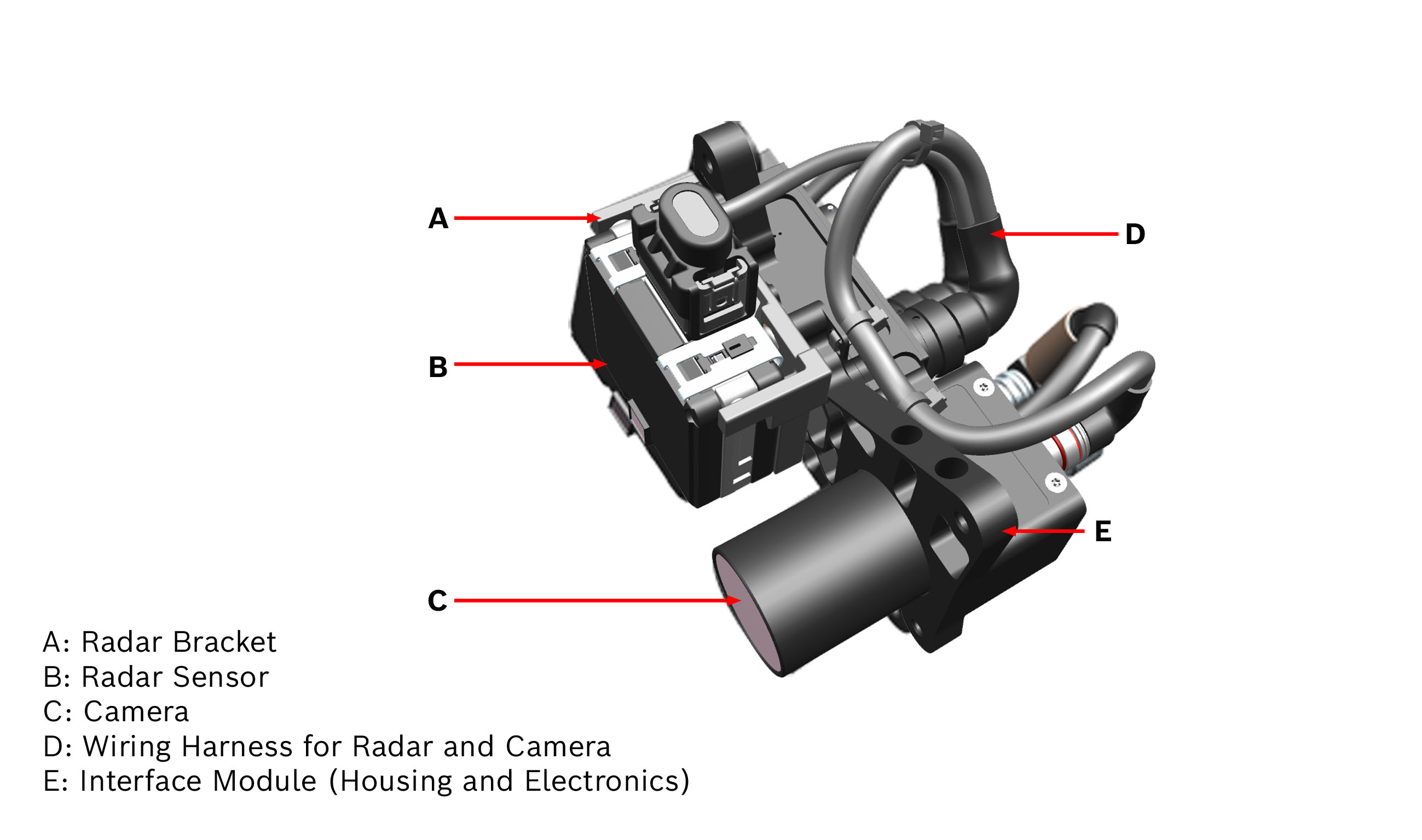
Consisting of parts (A) to (E)
Order number: F02U.V02.630-02
Radar Bracket (A)
Order number: F037.D00.084-01
Radar Unit (B)
Order number: F02U.V02.647-01
Camera Unit (C)
Order number: F02U.V02.799-01
Wiring Harness (D)
Order number: F02U.V02.802-01
Interface Module (Housing and Electronics) (E)
Order number: F02U.V02.639-01
Inertial Measurement Unit MM7.10
Order number: F02U.V03.092-01
Inertial Measurement Unit MM7.10
Wire with motorsport connector
Order number: F02U.V03.092-02
Inertial Measurement Unit MM7.10
Wire with open end
Order number: F02U.V03.092-90
Dimensions
Legal Restrictions
Generally blocked are direct and indirect business involving high risk destinations, including Russia, Belarus, Cuba, Iran, North Korea, Syria, Libya, Afghanistan, and certain non-governmental controlled Ukrainian regions. This list may change as geopolitics evolve.
