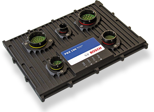
The PowerBox is an intelligent control and distribution unit for the electric grid in a modern racing car, which is seamlessly integrated into the Bosch Motorsport system architecture. It is capable to replace all conventional relays, fuses and circuit breakers, simplifies wiring harnesses and provides diagnostic capabilities. The integrated PBX-software guarantees an easy programming of complex functions by intuitive handling.
- Downloads
- Features
- Technical Specifications
- Communication
- Installation Notes
- Ordering Information
- Dimensions
- Upgrades
- Legal Restrictions
Downloads
Features
- 250 A continuous current
- 52 outputs, 48 V high side switches
- Ethernet, CAN and LIN communication
- Precision current measurement
- Easy programming of complex functions
Technical Specifications
Mechanical Data
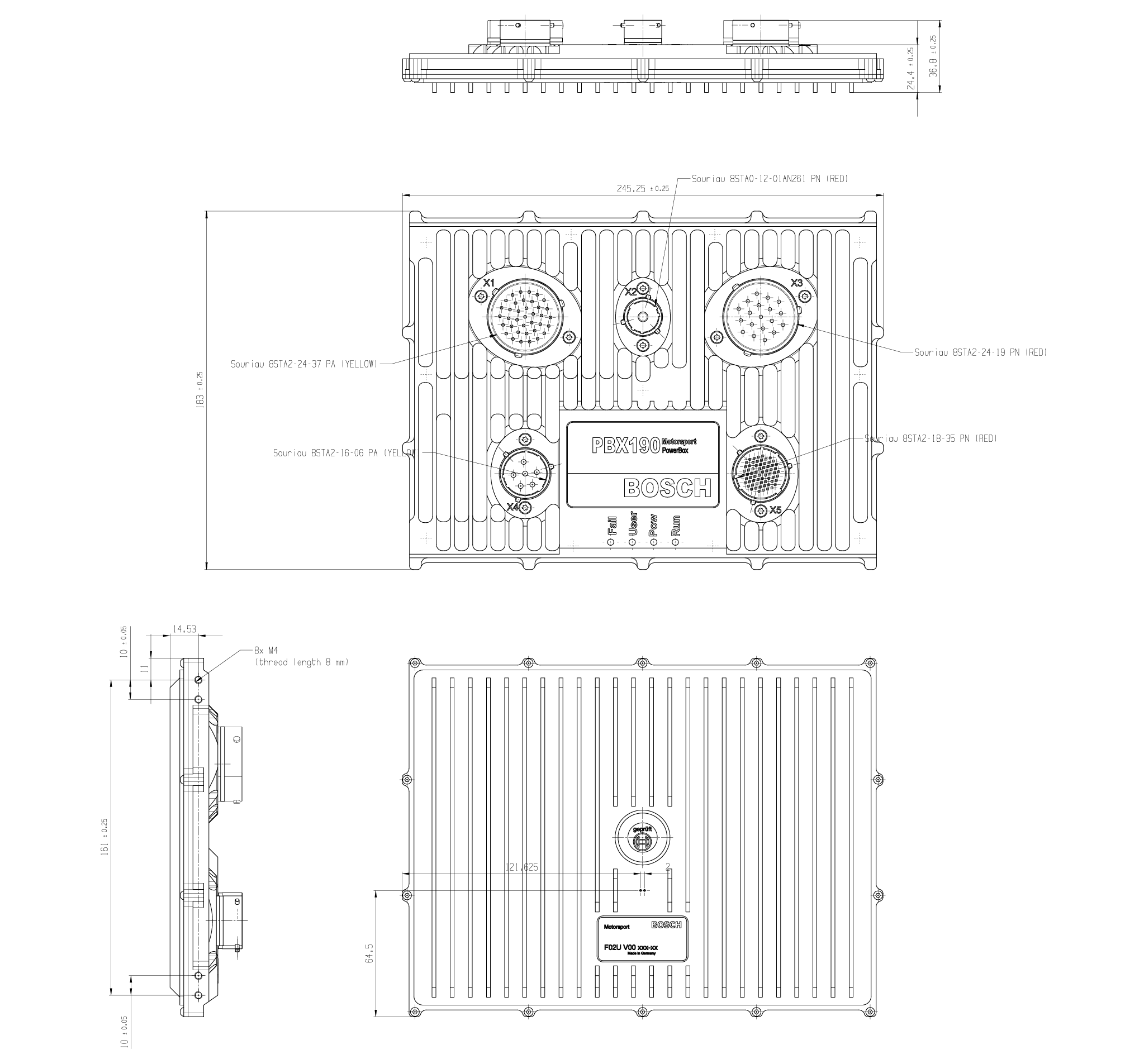
Size | 245 x 183 x 37 mm |
Weight | 1,270 g |
Protection Classification | IP67 |
Internal G-sensors |
|
Temp. range (at internal sensors) | -20 to 85°C |
Max. vibration | Vibration profile 1 (see Downloads) |
Electrical Data
Supply voltage range | 5 to 16 V |
Current consumption | <1 A continuously |
Maximum recommended output current | 250 A continuously; >310 A peak current (2 s) |
Inputs
18 x analog inputs (16 bit resolution) switchable pull-up resistors |
10 x digital inputs switchable pull-up/pull-down resistors |
Sensor Supplies and Screens
2 x sensor supplies 5 V 400 mA with individual ground pin |
Outputs
4 x high power channels up to 40 A (parallel up to 80 A) |
10 x high power channels up to 25 A |
26 x high power channels up to 15 A |
4 x high side channels up to 25 A, up to 48 V |
8 x multi-purpose outputs up to 15 A (low side, high side, push-pull, PWM; two output stages can be combined to form an H-bridge) |
Software
Function development and calibration tool | Bosch Motorsport PBX Suite |
Pin Configuration
Connector X1: 37 Pins / 8STA62437SA | |||
|---|---|---|---|
Pin | Signal | Cont. [A] | Peak [A] |
A | HS_15A X1_A | 15 | 100 |
B | HS_15A X1_B | 15 | 100 |
C | HS_15A X1_C | 15 | 100 |
D | HS_15A X1_D | 15 | 100 |
E | HS_15A X1_E | 15 | 100 |
F | HS_15A X1_F | 15 | 100 |
G | HS_15A X1_G | 15 | 100 |
H | HS_15A X1_H | 15 | 100 |
J | HS_15A X1_J | 15 | 100 |
K | HS_15A X1_K | 15 | 100 |
L | HS_15A X1_L | 15 | 100 |
M | HS_15A X1_M | 15 | 100 |
N | HS_15A X1_N | 15 | 100 |
P | PWM_15A X1_P | 15 | 60 |
R | PWM_15A X1_R | 15 | 60 |
S | PWM_15A X1_S | 15 | 60 |
T | PWM_15A X1_T | 15 | 60 |
U | HS_15A X1_U | 15 | 100 |
V | HS_15A X1_V | 15 | 100 |
W | HS_15A X1_W | 15 | 100 |
X | HS_15A X1_X | 15 | 100 |
Y | HS_15A X1_Y | 15 | 100 |
Z | HS_15A X1_Z | 15 | 100 |
a | HS_15A X1_a | 15 | 100 |
b | HS_15A X1_b | 15 | 100 |
c | PWM_15A X1_c | 15 | 60 |
d | PWM_15A X1_d | 15 | 60 |
e | PWM_15A X1_e | 15 | 60 |
f | PWM_15A X1_f | 15 | 60 |
g | HS_15A X1_g | 15 | 100 |
h | HS_15A X1_h | 15 | 100 |
k | HS_15A X1_k | 15 | 100 |
m | HS_15A X1_m | 15 | 100 |
n | HS_15A X1_n | 15 | 100 |
p | Power KL31 | 15 | - |
q | Power KL31 | 15 | - |
r | Power KL31 | 15 | - |
Connector X2: 1 Pin / 8STA61201BN261 | |||
|---|---|---|---|
Pin | Signal | Cont. [A] | Peak [A] |
1 | Power Supply 12 V | 200 | 240 |
Connector X3: 19 Pins / 8STA62419SN | |||
|---|---|---|---|
Pin | Signal | Cont. [A] | Peak [A] |
A | HS_25A X3_A | 25 | 150 |
B | HS_25A X3_B | 25 | 150 |
C | HS_25A X3_C | 25 | 150 |
D | HS_25A X3_D | 25 | 150 |
E | HS_25A X3_E | 25 | 150 |
F | HS_25A X3_F | 25 | 150 |
G + H | HS_40A X3_G_H | 40 | 150 |
J + T | HS_40A X3_J_T | 40 | 150 |
K + U | HS_40A X3_K_U | 40 | 150 |
L + N | HS_40A X3_L_N | 40 | 150 |
M | HS_25A X3_M | 25 | 150 |
P | HS_25A X3_P | 25 | 150 |
R | HS_25A X3_R | 25 | 150 |
S | HS_25A X3_S | 25 | 150 |
V | Power KL31 | 25 | - |
Connector X4: 6 Pins / 8STA61606SA | |||
|---|---|---|---|
Pin | Signal | Cont. [A] | Peak [A] |
A | HS48V_25A X4_A | 25 | 50 |
B | HS48V_25A X4_B | 25 | 50 |
C | HS48V_25A X4_C | 25 | 50 |
D | HS48V_25A X4_D | 25 | 50 |
E | Supply up to 48 V for X4 | 25 | 35 |
F | Supply up to 48 V for X4 | 25 | 35 |
Connector X5: 66 Pins / 8STA6-18-35SN | ||
|---|---|---|
Pin | Signal |
|
1 | Analog Input X5_01 | 0 to 5 V, Pull-up |
2 | Analog Input X5_02 | 0 to 5 V, Pull-up |
3 | Analog Input X5_03 | 0 to 5 V, Pull-up |
4 | Analog Input X5_04 | 0 to 5 V, Pull-up |
5 | Analog Input X5_05 | 0 to 5 V, Pull-up |
6 | Analog Input X5_06 | 0 to 5 V, Pull-up |
7 | Analog Input X5_07 | 0 to 5 V, Pull-up |
8 | Analog Input X5_08 | 0 to 5 V, Pull-up |
9 | CAN 3 Interface Low-Level | Max. 1 Mbaud |
10 | Analog Input X5_10 | 0 to 5 V, Pull-up |
11 | Analog Input X5_11 | 0 to 5 V, Pull-up |
12 | Analog Input X5_12 | 0 to 5 V, Pull-up |
13 | Digital Input X5_13 | 0 to 12 V, Pull-up, Pull-down |
14 | Digital Input X5_14 | 0 to 12 V, Pull-up, Pull-down |
15 | CAN 3 Interface High-Level | Max. 1 Mbaud |
16 | LIN | Control of Bosch Motorsport LIN devices included. Support of other devices on request. |
17 | Analog Input X5_17 | 0 to 5 V, Pull-up |
18 | Analog Input X5_18 | 0 to 5 V, Pull-up |
19 | DGND-fused | 5 A |
20 | DGND-fused | 5 A |
21 | Digital Input X5_21 | 0 to 12 V, Pull-up, Pull-down |
22 | Digital Input X5_22 | 0 to 12 V, Pull-up, Pull-down |
23 | do not connect (use for internal debugging) | |
24 | do not connect (use for internal debugging) | |
25 | do not connect (use for internal debugging) | |
26 | do not connect (use for internal debugging) | |
27 | Analog Input X5_27 | 0 to 5 V, Pull-up |
28 | Digital Input X5_28 | 0 to 12 V, Pull-up, Pull-down |
29 | Digital Input X5_29 | 0 to 12 V, Pull-up, Pull-down |
30 | Analog Input X5_30 | 0 to 5 V, Pull-up |
31 | KL31-fused |
|
32 | do not connect (use for internal debugging) | |
33 | do not connect (use for internal debugging) | |
34 | do not connect (use for internal debugging) | |
35 | do not connect (use for internal debugging) | |
36 | Digital Input X5_36 | 0 to 12 V, Pull-up, Pull-down |
37 | Digital Input X5_37 | 0 to 12 V, Pull-up, Pull-down |
38 | Analog_Screen |
|
39 | Analog Input X5_39 | 0 to 5 V, Pull-up |
40 | KL31-fused |
|
41 | do not connect (use for internal debugging) | |
42 | do not connect (use for internal debugging) | |
43 | Digital Input X5_43 | 0 to 12 V, Pull-up, Pull-down |
44 | Digital Input X5_44 | 0 to 12 V, Pull-up, Pull-down |
45 | Sensor GND for X5_51 | 5 A |
46 | Timesync |
|
47 | COM_Screen |
|
48 | CAN 1 Interface High-Level | Max. 1 Mbaud |
49 | do not connect (use for internal debugging) | |
50 | do not connect (use for internal debugging) | |
51 | Powersupply_5V X5_51 | 400 mA |
52 | Sensor GND for X5_58 | 5 A |
53 | ETHERNET1 RXN | 10/100 Mbps |
54 | ETHERNET0 RXN | 10/100 Mbps |
55 | CAN 2 Interface Low-Level | Max. 1 Mbaud |
56 | CAN 1 Interface Low-Level | Max. 1 Mbaud |
57 | Analog Input X5_57 | 0 to 5 V, Pull-up |
58 | Powersupply_5V X5_58 | 400 mA |
59 | ETHERNET1 RXP | 10/100 Mbps |
60 | ETHERNET1 TXN | 10/100 Mbps |
61 | ETHERNET0 TXN | 10/100 Mbps |
62 | CAN 2 Interface High-Level | Max. 1 Mbaud |
63 | Analog Input X5_63 | 0 to 5 V, Pull-up |
64 | ETHERNET1 TXP | 10/100 Mbps |
65 | ETHERNET0 RXP | 10/100 Mbps |
66 | ETHERNET0 TXP | 10/100 Mbps |
Communication
3 x CAN |
|
2 x Ethernet |
|
1 x LIN, Control of Bosch Motorsport LIN devices included. Support of other devices on request. | |
Installation Notes
Inspection services recommended after 220 h or 2 years, no components to replace. |
Ordering Information
PowerBox PBX 190
Order number: F02U.V02.626-04
Software Options
CCA Hardware Upgrade per device
Order number: F02U.V02.137-01
Accessories
Mating Connector X1
Order number: F02U.004.387-01
Mating Connector X2
Socket 25 mm²
Order number: F02U.B01.044-01
Mating Connector X2
Socket 35 mm2
Order number: F02U.B01.045-01
Mating Connector X3
Order number: F02U.004.386-01
Mating Connector X4
Order number: F02U.004.388-01
Mating Connector X5
Order number: F02U.000.472-02
Connector Opening Tool for Shellsize 24
Order number: F02U.V02.434-01
Breakout Box
Order number: F02U.V02.523-01
CAN Keypad CK-M12
Order number: F02U.V0U.328-04
Dimensions

Upgrades
CCA Hardware Upgrade per device
Provides the option to run customer developed software code on Bosch device |
Legal Restrictions
Generally blocked are direct and indirect business involving high risk destinations, including Russia, Belarus, Cuba, Iran, North Korea, Syria, Libya, Afghanistan, and certain non-governmental controlled Ukrainian regions. This list may change as geopolitics evolve.
